How I Built HelioHex
For the past three months, I’ve been building a highly configurable, modular, hexagon-based lighting system from scratch that is controllable from any device and syncs to Spotify. Here’s a demo:
Here’s some of the highlights of HelioHex:
- Different lighting ‘modes’
- Set the color of the whole display
- Set the color of individual hexagons
- Generate a random aesthetically-pleasing color palette
- Sync the color of the display to the time of the day
- Spotify integration
- Matches up the colors of each hexagon to the features of the song playing
- Changes depending on the emotions of the song e.g. sadder songs are more blue
- Adaptable web controller
- Use any device on the network to control the device
- Control all the different modes and brightness of the display
- Shows a virtual visualization of the display
- Flexible design
- Arrange the hexagons in whatever pattern you like - change the settings in one file and everything automatically updates
- Expand the structure easily if you build more hexagons
Table of Contents
Inspiration
Late March, I realized that all my schoolwork and testing would soon be over. In an effort to avoid spending my quarantine solely indulging in video games and Netflix, I sought a project.
While brainstorming ideas, I came across the Nanoleaf Light Panels, a vibrant lighting system that gamers frequently display in their rooms. I thought that I could extend the functionality of this to show lights based off events, like if I received a notification on my phone. And maybe Facebook notifications could be blue, Snapchat notifications yellow, and email notifications red. All of the pieces of this project were starting to come together until I saw the pricetag: $200.
Nope. No way was I gonna spend $200 on some lights. To make it worse, that was the price for nine measely panels. Don’t get me wrong - it looked impressive, just not worth a little over $20 per panel. And even if I still wanted it, the $200 set was sold out - I’d have to cough up $300 for fifteen panels instead.
Perhaps the coolest application of the Nanoleaf Light Panels is the Rhythm Edition, which syncs your lighting system to music. Watching the demo left me… disappointed. It was highly customizable, but perhaps too customizable. I just wanted to click a button and have the lighting system sync up to all the nuances in the song - if the song was going to have the bass drop, I wanted to emphasize that and to make the lights to feel alive. Maybe I’m in the minority here, but I was pretty unsatisfied - especially considering I’d be shelling out hundreds of dollars for this.
Then something clicked; why don’t I just build my own system? I could customize it to my heart’s desire and I could make it for a lot cheaper than $200. I would also learn a lot from this project - it seemed perfect. And so, I set out to build my own lighting system - HelioHex.
Research
As should be with any project, the first step was research. This DIY video from NerdForge looked very similar to what I wanted. The key features I wanted to adopt from this was the modularity, the hexagon design (because it looked really cool), and the remote controller. However, I felt the app he developed didn’t make the most of the lights - specifically, I wanted to sync up my own system with Spotify. Also, he 3D-printed the frame for the hexagons. Unfortunately, I do not have the luxury of a 3D-printer (and I couldn’t 3D-print at the library due to the lockdown). This motivated me to alternatively make a wooden frame to give off a sleek, less-manufactured look.
I also checked out many more guides that helped me frame my goals. Ultimately, this research helped me answer one big question: was this project attainable?
The answer was a confident ¯\(ツ)/¯. A lot of the electronics scared me and the coding seemed decently formidable. I like challenges, though, so I went for it. Also, given that I had boatloads of free time, it seemed like I had nothing better to do.
Vision
The next step for me was to create a concrete vision of my desired end-result. First up were the non-negotiables - things my project HAD to have to consider it successful:
- Working lights that are easily controllable by a remote controller
- Seamless integration with a music app
- Modularity - changing the arrangement of the hexagon units should be relatively easy
- Self containment - each unit is independent of other units
- Preset lighting modes that “look nice”
- A clean UI for the remote controller
Next up were some nice to haves - not needed, but would make me feel really accomplished
- No hard coding
- Anyone should be able to control the lighting system
- Each individual hexagon “unit” can have their color set
Some of these goals were scary, especially when you combine them together - having the ability to set individual hexagon colors without hardcoding while having the UI of the remote controller look clean? Yeesh.
The next step was materializing this vision. What helped me was using a Kanban Board. I wrote mini tasks for myself to reach different goals - divided into sections like software, hardware, and construction and prioritized by importance. A Kanban Board made this ambitious project much more digestable. It also made sure that I wouldn’t spend time on unnecessary, small fixes unless they were needed. The goal was to build the system as quickly as possible, and then go back and optimize it. Basically the Agile Development Technique. Totally see how helpful it is now and why companies emphasize it so heavily.
Construction
Materials
| Material | Cost |
|---|---|
| LED Strip | $29.90 |
| JST Connectors | $10.99 |
| RF Remote Controller | $8.99 |
| Plywood | $10.96 |
| Acrylic Light Panel | $12.48 |
| Raspberry Pi 4 | $35.00 |
| Power Supply | $20.99 |
| Wires x3 | $18.81 |
| Cord Cover | $8.12 |
| Hot glue, super glue, push pins, clamps, etc. | $30.00 |
| Total | $186.24 |
I got under my goal of $200! Ended up saving about $15 for three months of my time.
To be fair, I did buy other materials that I never ended up using and did not account for tax. This means that the actual cost of this project probably was $50-$100 higher, but we’ll just say it’s under $200 because it makes me feel better.
Wooden Frames
The first legitimate step in the project was to create the casing for each unit. All the guides I found used 3D printed cases, which was inaccessible for me, so I used wood. I bought a 24” by 12” wooden sheet and cut it out into rectangular pieces. I used a hexagon shape for each unit so I had to glue six of these rectangles together. I hotglued a metal hinge into the shape of a 120° angle and used that as a reference to put the rectangles together. The structural integrity of each hexagon was important so I used a trifecta of super glue, hot glue, and wood glue.
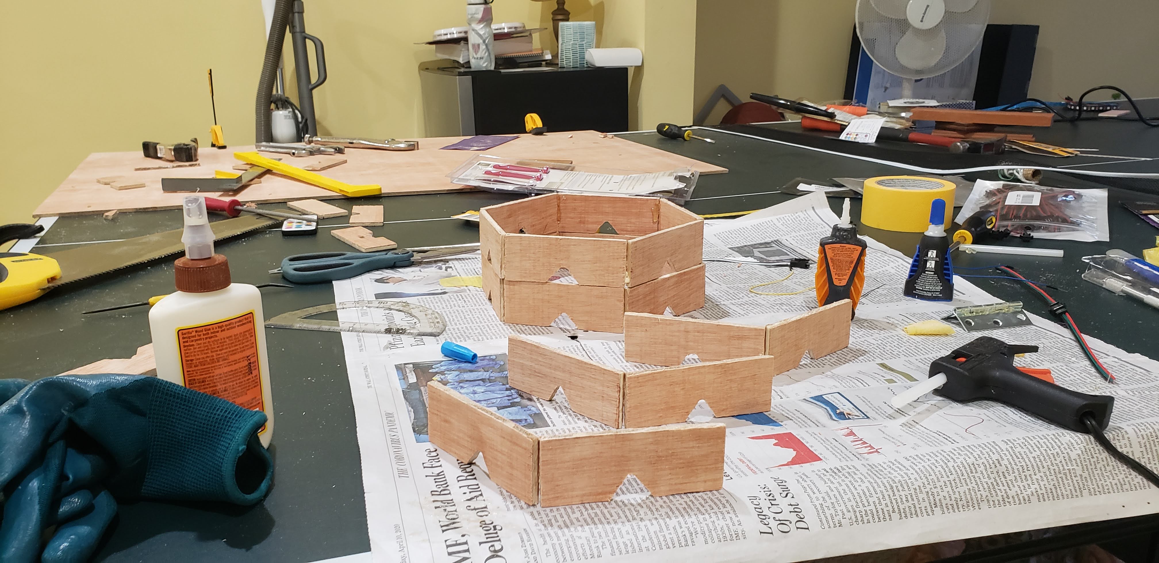 Wooden hexagon construction. In the foreground, wooden side pairs are joined together that will eventually form full hexagons. In the background, you see that my worktable was a messy ping-pong table.
In the above picture, you’ll notice small triangles cut out at the bottom of each plywood piece. This allows for wires to pass through connecting units. In line with my goal of modularity, this cutout was on every side so I could configure my system however I’d like. I made eight of these units, the most I could make given the length of the LED strip.
Light Diffusion
The goal of this lighting system was to have each hexagon display a uniform, individual color. To achieve this uniformity, the material on top of each hexagon must evenly diffuse light from the LED strip that lines the inner perimeter of each hexagon.
This is where the acrylic sheet comes in. The sheet I bought is basically the same material as the light panels that covers school ceilings.
The problem is that acrylic is very brittle to the point that any cut I made - using scissors, a saw, even with the knife Home Depot recommended - completely fragmented the acrylic. After spending a week trying to figure it out, I decided to hold it off till I could laser cut it when the lockdown lifted.
In the meanwhile, I used a poor man’s acrylic - paper. It served its purpose for how easy it was to use.
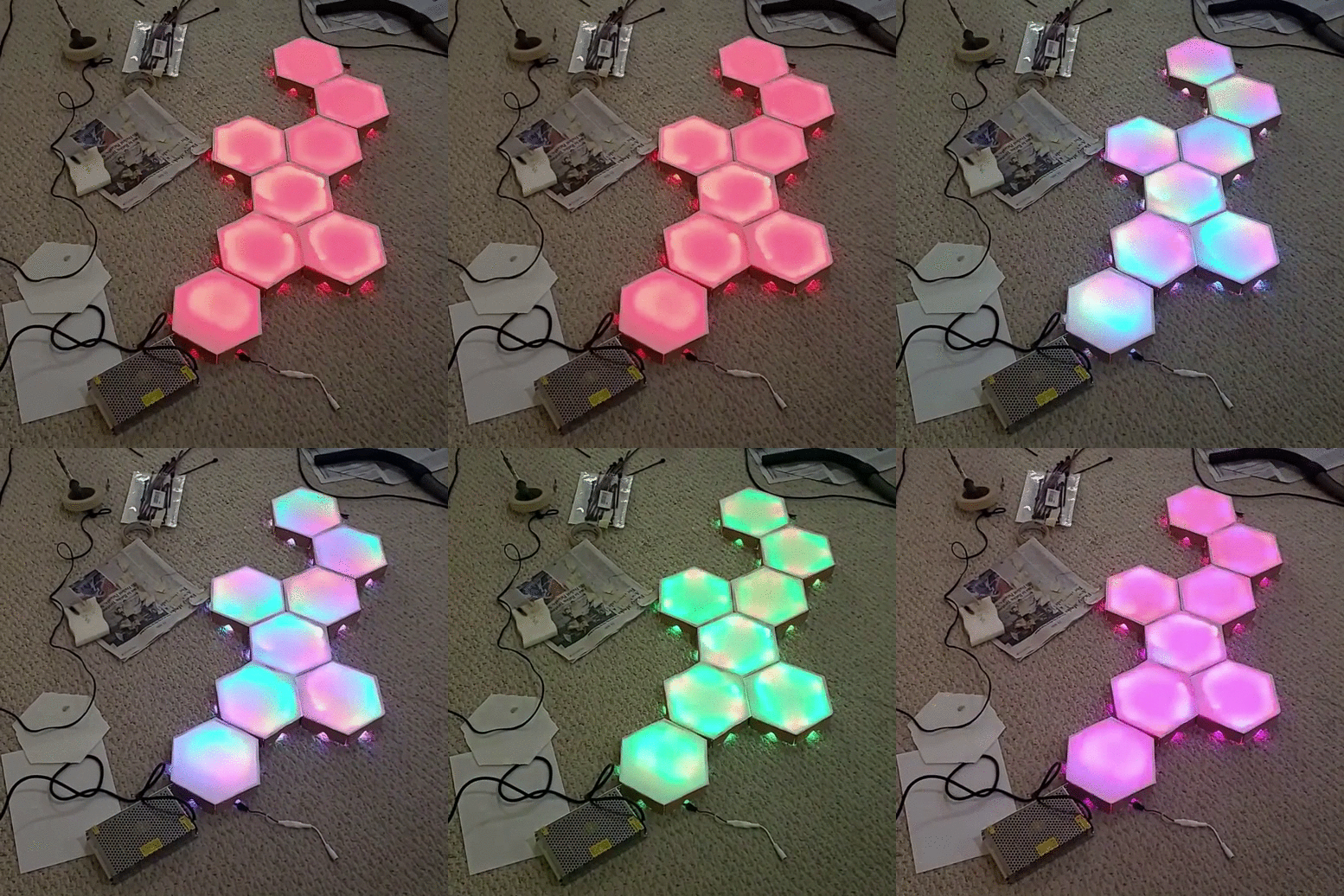 Paper hexagons put on top of each unit. The lighting is controlled by a cheap RF remote.
Although it does look pretty cool, there’s a couple of problems. First, it’s not clean. Paper doesn’t give off that professional vibe I’m striving for and if I’m spending months on this, might as well make it look good. Second, paper is really flimsy. It wouldn’t stick well with tape, and I didn’t want a permanent solution like glue because I knew I wanted to change it eventually. Lastly, it doesn’t diffuse the light THAT well; it does the job, but it’s nothing amazing.
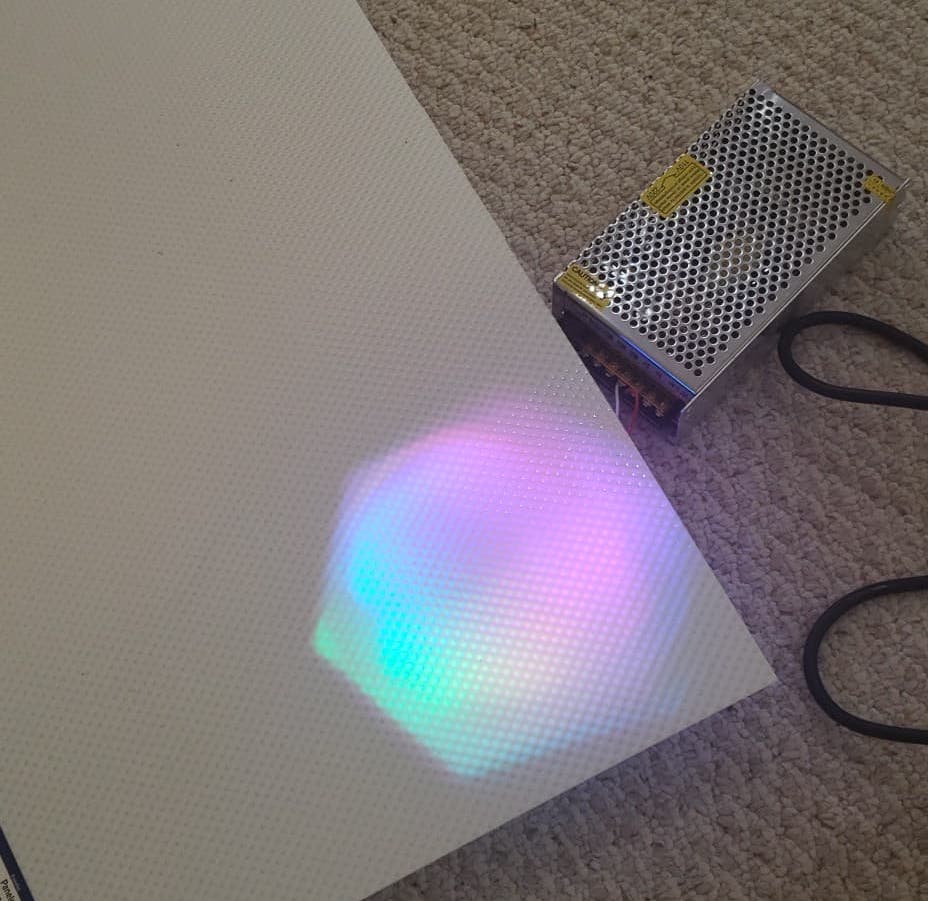 The uncut acrylic sheet on top of a lit unit.
These images don’t do justice to the acrylic sheet. It looks miles better with material that’s meant to diffuse light. Instead of waiting for a laser cutter for who knows how long, I got lucky when a friend allowed me to borrow their hand-held circular saw. The fine teeth on this allowed me to cut the acrylic with no worry.
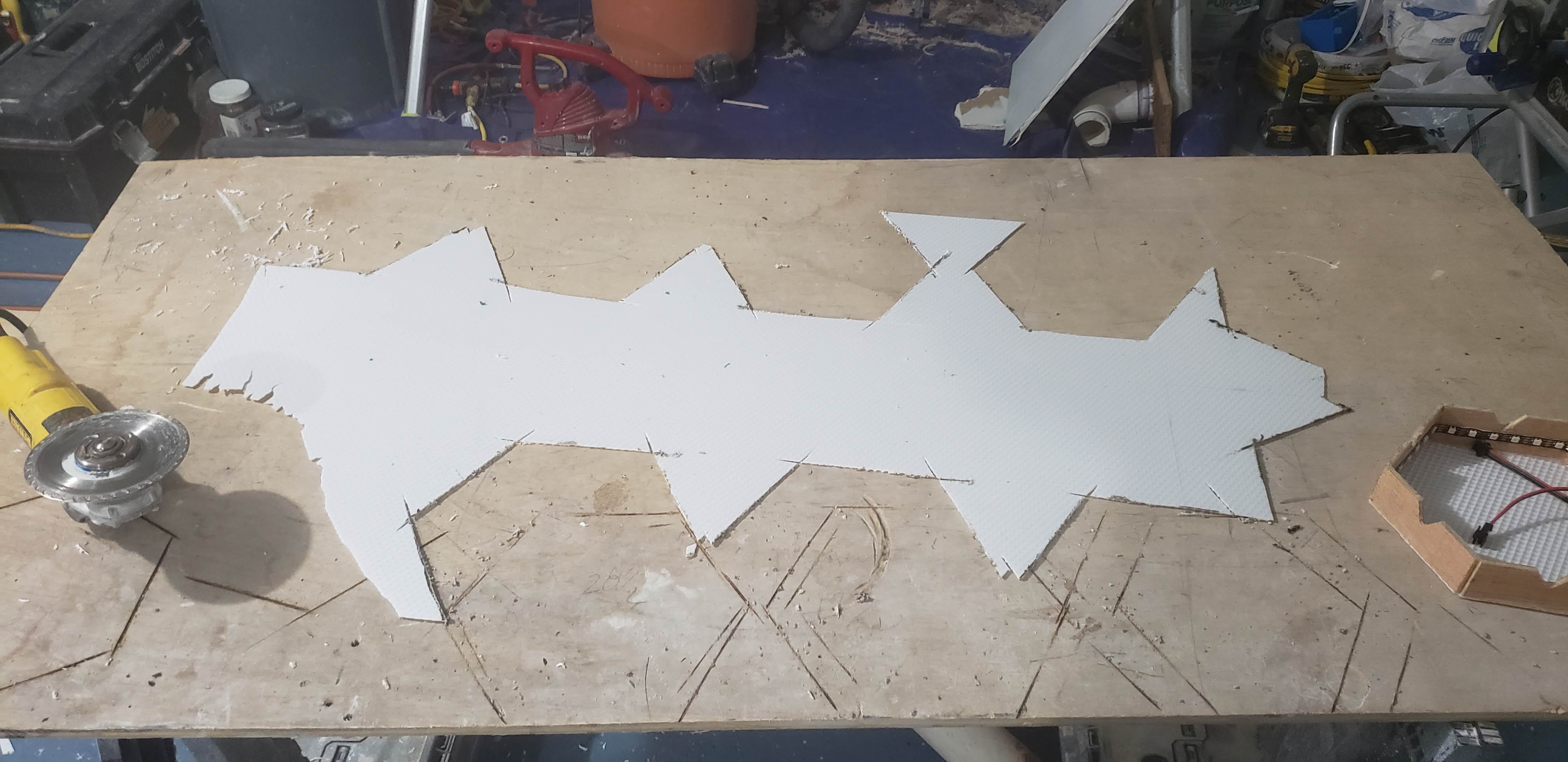 The acrylic sheet after I cut it. On the left of the sheet you can see the jaggedness resulting from my previous methods.
It turned out a success! I hotglued the cut-out acrylic pieces to the hexagons and shaved down the sharp edges.
Electronics
This is what I was worried about the most. Despite having taken multiple classes in high school dealing with electronics, I had no idea what I was doing - evident by me almost setting the house on fire a few times.
Wiring Lights
I cut up the light strip to put 36 LEDs in each hexagon unit. Each LED draws 50mA at full brightness, meaning for eight hexagons, I would need 14.4 Amps as a current. This is a lot of current, so needless to say, I was a bit worried. I followed a simple tutorial to wire the lights and it worked pretty well to my delight.
I then soldered JST connectors to both ends of the LED strip in each unit. This would achieve my goal of modularity.
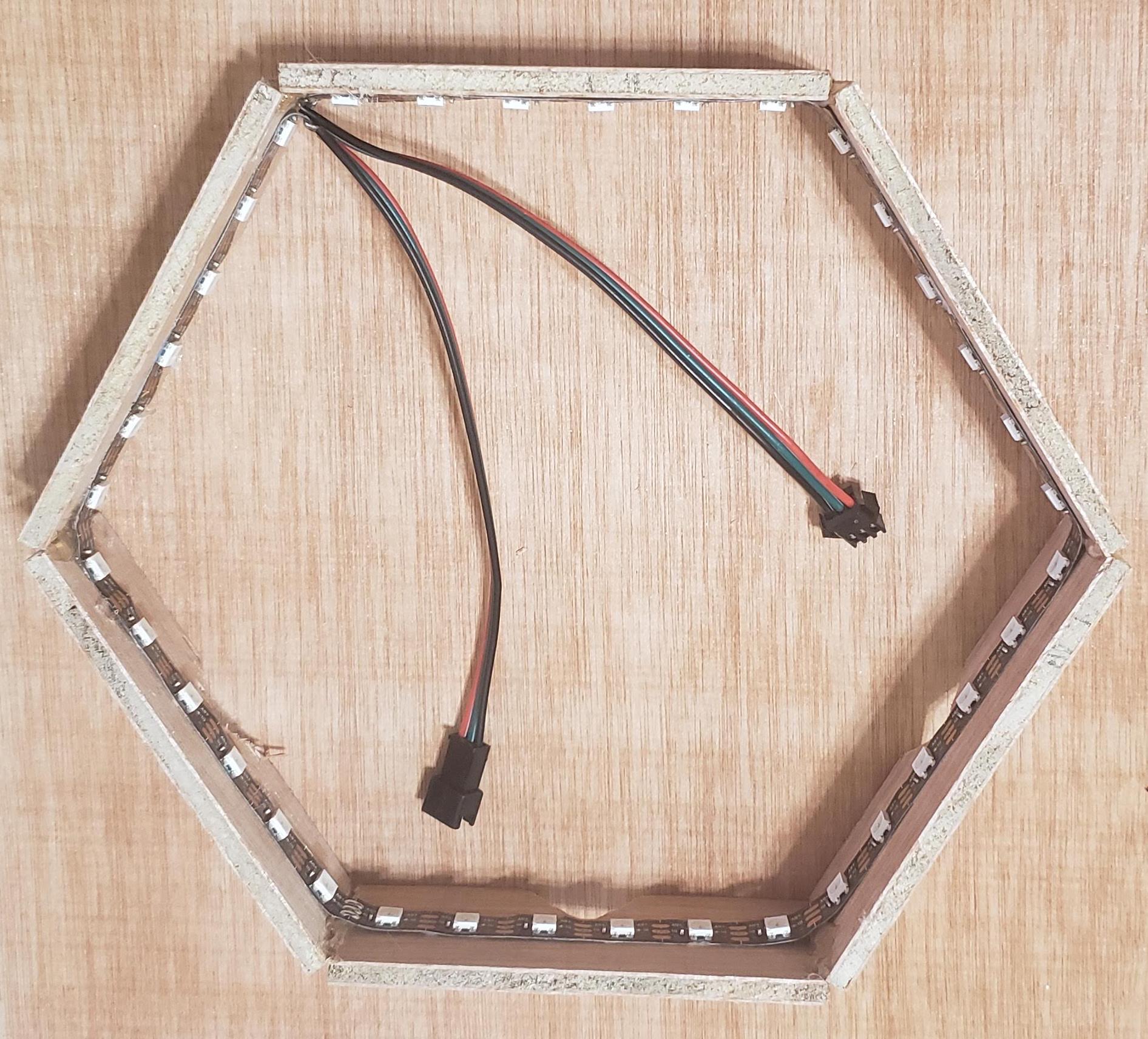 A basic unit with JST connectors soldered onto the ends.
Supplying Current
In my idealistic world, after I wired each unit, I wouldn’t have to ever touch the electronics again. Unfortunately, there wasn’t enough power going through all the hexagons.
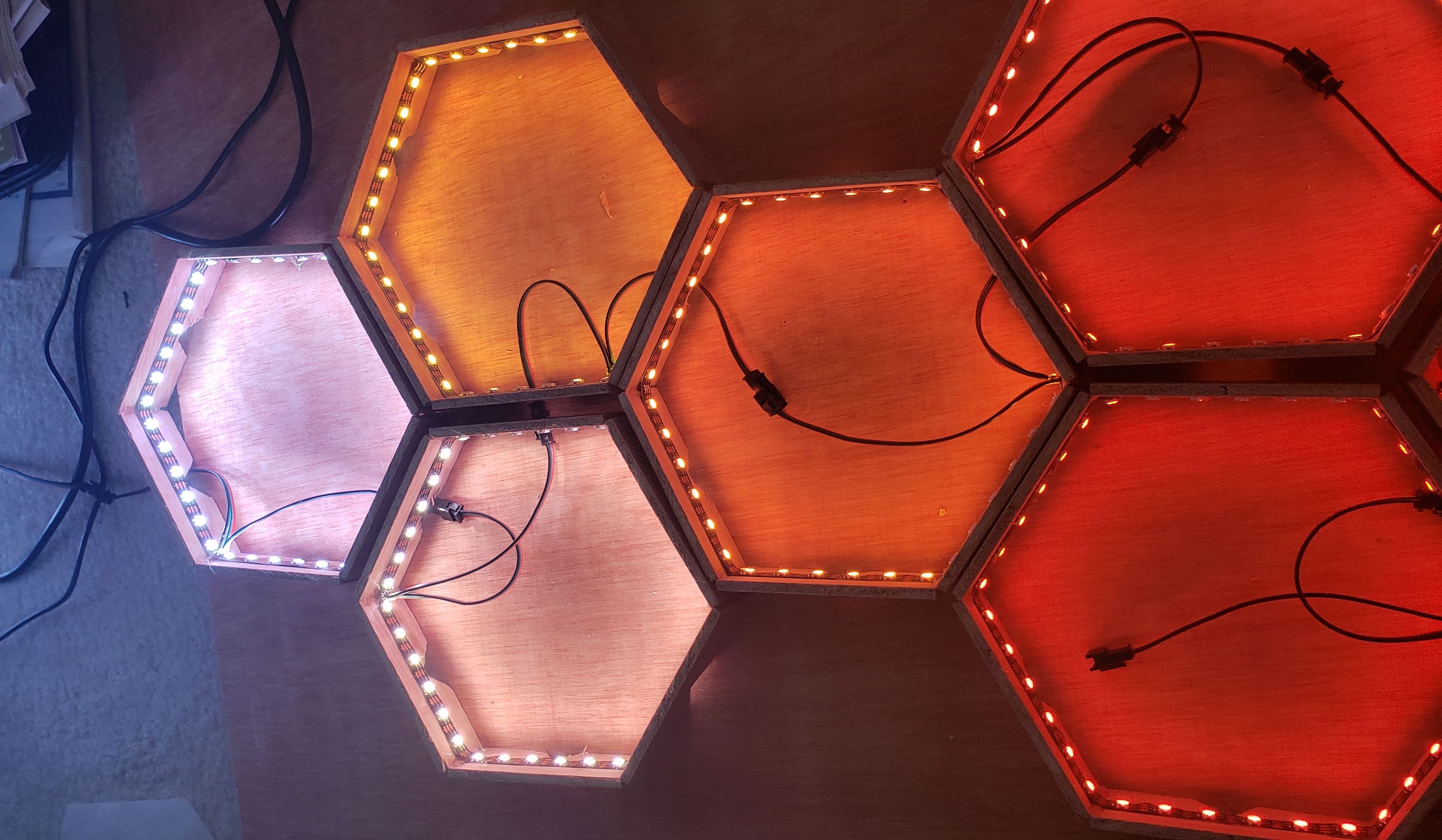 All of the hexagons are set to white at max brightness, but insufficient power results in later hexagons only showing the red channel.
I needed some way to pass the 5V and the ground line to each hexagon without passing through the LEDs, which would draw power. My solution was allowing the power to bypass most LEDs in parallel by connecting the 5V and ground at the ends of the LED strip in each unit.
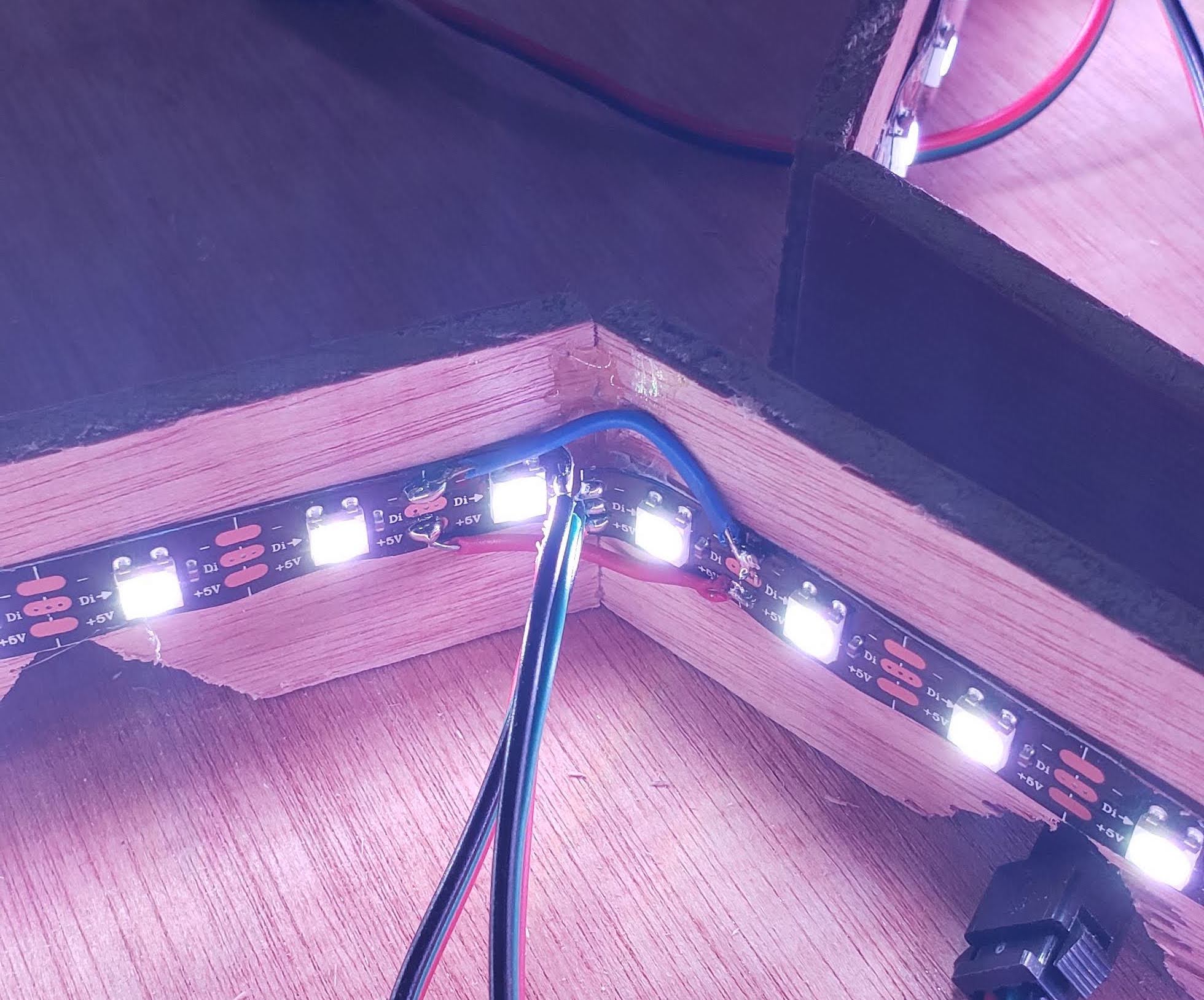 The solution to the power issues. The blue wire connects the grounds and the red wire connects the 5V.
To my surprise, it worked!
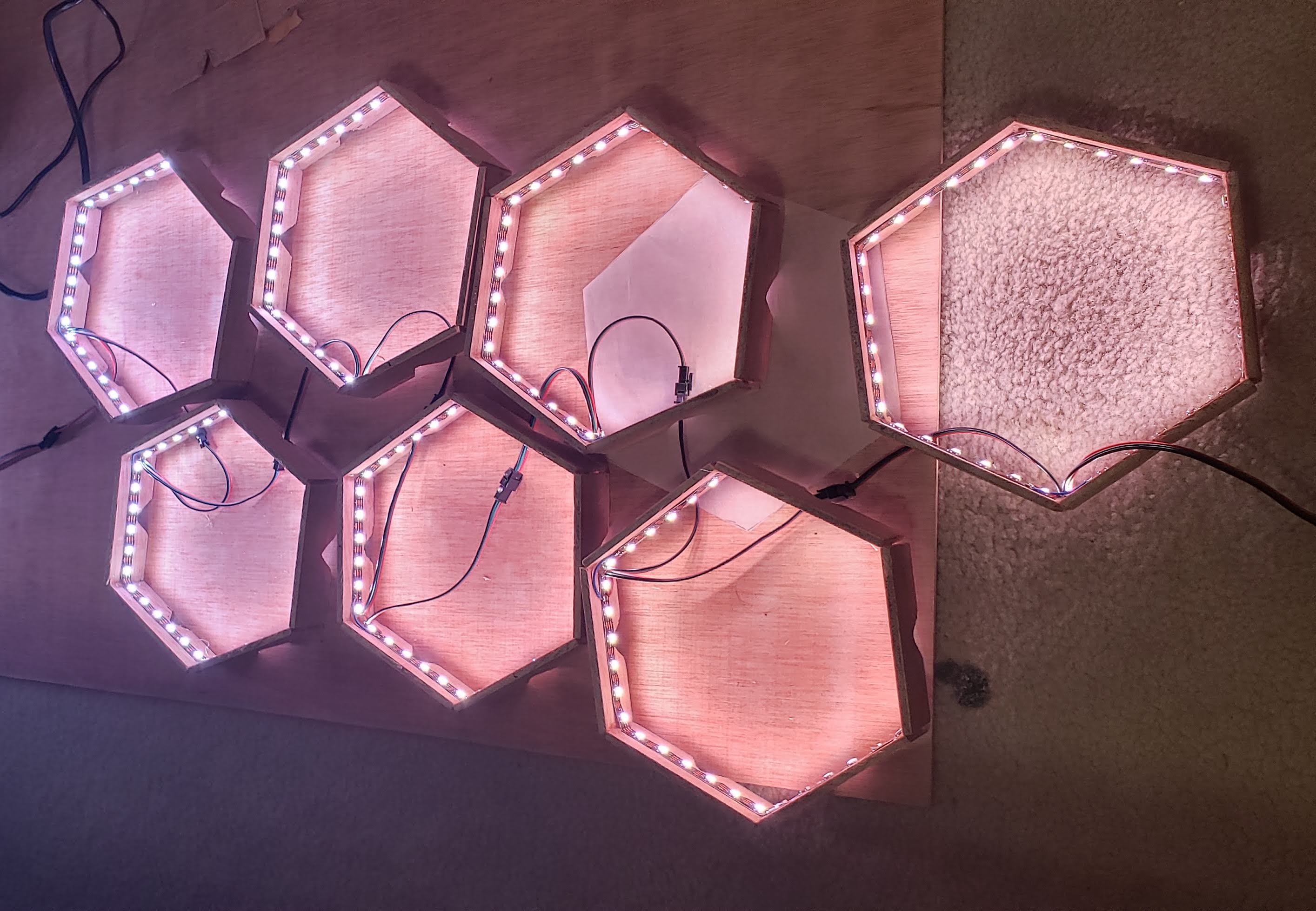 All of the hexagons are set to white at max brightness again. Not too bad!
You can still see some of the color fading away, but it’s much better. The reason it isn’t perfect is because the way I wired it requires the power to go through two LEDs in each unit before going to the next unit.
Extending Wires
My nightmares of soldering still didn’t end. In order to hang the display on the wall, I would need to extend the wires to at least to five feet. The problem was that when I soldered the longer wires, the LEDs started flickering randomly. Weirdly, when I touched the input data wire, everything worked perfectly.
After hours (and hours and hours) of research (the issue was common-mode noise?), and a brief scare that I shorted and burnt all of the LEDs 😬, it turned out that all I needed was a resistor in series for the data input wire. Go figure.
I packed all the wires into a sleek wire cover and stuck it against the wall.
Safety
With such a massive power supply, I needed to ensure it wouldn’t be on 24/7 so it would be safe and not drive up the electricity bills. I had a Wemo Smart Plug lying around that could turn plugs on and off from an app. This allowed me to monitor and control the power supply from within Wemo’s app. I also found a way to switch the plug’s state from my code as well, which gave me more flexibility in controlling the display.
Software
Whenever I work on side projects, my code tends to get really messy and isn’t usually thought out well. This time, I actively attempted to make my code flexible so that it wouldn’t be a pain to reconfigure if I ever came back to this project.
 My plan for how everything would work. At the core, a website pings endpoints on a Flask server hosted on a Raspberry Pi.
I put together different classes that would allow me to control each hexagon (check out the code here). I could control each light because I bought individually-addressable LEDs, which allow me to manipulate each LED independently (which is why they cost an appreciable amount more than normal LEDs). To make my project flexible, whenever I would change the arrangement of the hexagons, all I would need to do is change one settings file. I’m only going to explain the most interesting parts of the code (but feel free to check it all out to see how it all comes together).
Spotify Syncing
The coolest feature of this project is easily the ability to sync up to music. The straightforward way to do this would be to have the Raspberry Pi capture any audio, process it with a Fast Fourier Transform, and display the lights. Using this method, however, requires a mic for the Raspberry Pi, which is a) more money and b) more electronics.
My solution was to use the Spotify API to extract information about the song playing. This would constrain me to only use Spotify, which was okay considering that was the only application I cared about. I would also have to do much more processing because Spotify’s information about songs is more obscure than raw audio waves, in my opinion (which makes sense since someone shouldn’t be able to reconstruct the song from the data Spotify provides).
I started with research. This video helped me understand music theory with Spotify. This code was the only code I could find that was related to my project, but it doesn’t use hexagon lights, just a straight line of LEDs. Regardless, it helped me frame this portion of the project.
Spotify provides its data in discrete information about different segments of each song. After I receive this information, I construct continuous functions for the loudness of the song at any point in time. This gives a loudness value that corresponds to the brightness of the display.
For adjusting the hue of each hexagon, I construct probability distributions on the pitch data for any moment in time, which I sample from to get a hue value for each hexagon. Using a probability distribution introduces some entropy instead of showing the same animation for a song every time.
How do I determine which pitch corresponds to which hue? This talk blew my mind for so many reasons, but the relevant portion shows how pitch can correlate to hue (check out the diagram at 33:13 to see the chart with these correlations). I’m not going to describe it here, but the video is 100% worth your time.
The biggest issue I encountered was aligning the display to the exact time of the song. Obviously, if the display isn’t aligned to the song, it’s very noticeable, especially when the beat drops. By the time Spotify returns the current time that the song is at, that time for the song has changed. Spotify does return a timestamp when the data was fetched, but that information is incorrect and hasn’t been fixed for two years.
I usually am able to find some hacky solution to these types of problems, but I honestly couldn’t find anything. It still annoys me, but I settled for the unsatisfying solution of estimating the lag at one second which works out alright.
Beyond that, I added some nice features to add biases for the hue depending on the emotions in a song and to add specific color sequences emphasizing the peaks of a song.
Web App Controller
I wanted some accessible way to control the light display, so I decided to build a website (much better than an app because I could let guests control the system without them needing to download anything). As with all websites I design, I built a mockup for how I wanted it to look like.
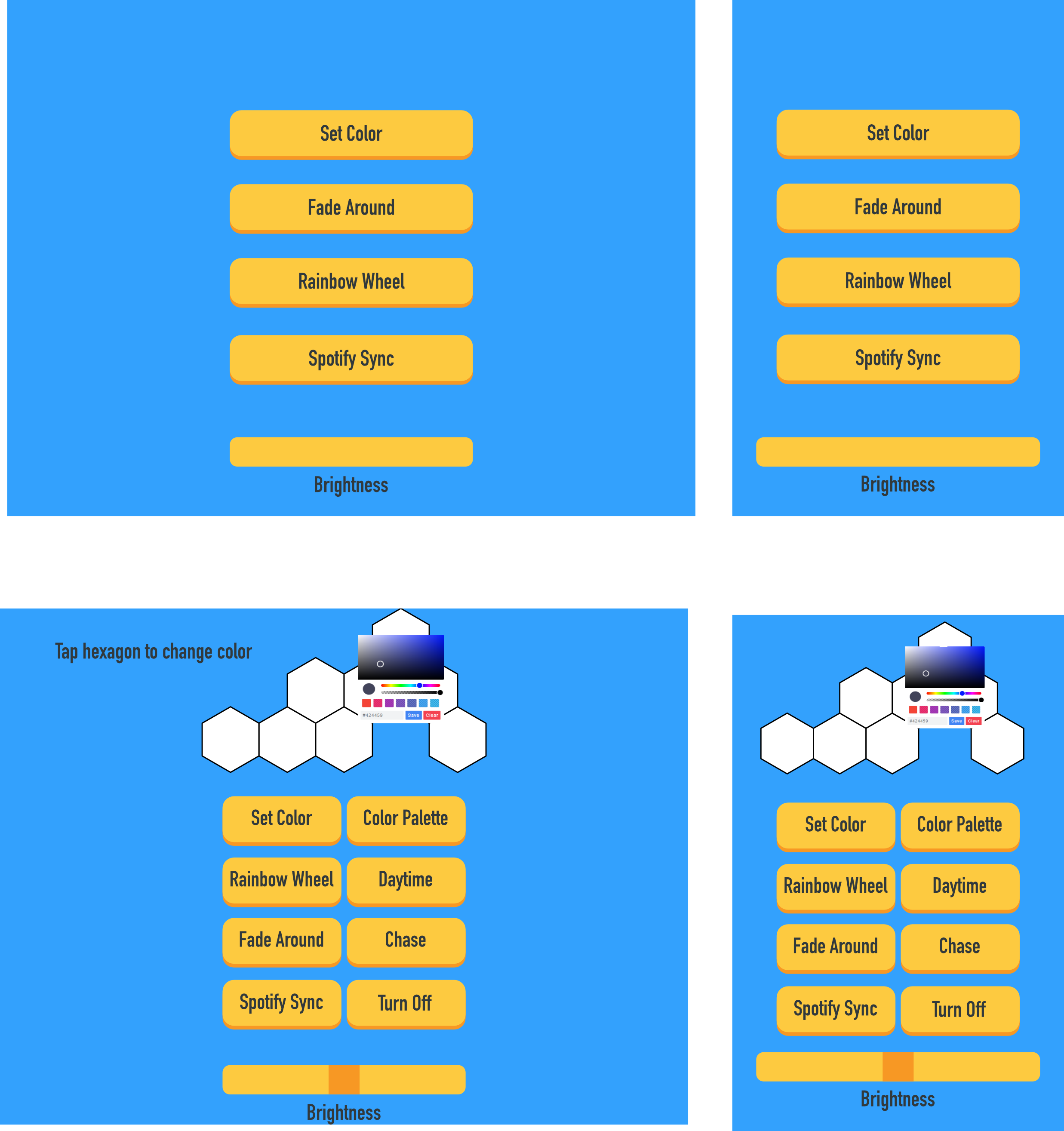 Mockup for the website controller. The top row shows the original mockup and bottom row shows a revised version. The left column is the display on a laptop and the right column shows a mobile view of the website.
I built the website and deployed it to Heroku at http://heliohex.herokuapp.com (it might take a few seconds to load because I’m using the free version). Each button allows for different “modes” to control the lights. The hexagon display on the screen is generated based off the current layout and lets me change each individual hexagon color (something I’m really proud to have gotten to work!).
To communicate between the web controller and Raspberry Pi, the web controller pings different endpoints on a Flask server running on the Pi, which accordingly changes different colors on the display. The Flask server is on my home network, so you can access the web controller from anywhere, but it’ll only work when connected to my home’s WiFi. The astute may notice that the web controller uses an HTTP header and not an HTTPS header. Because of CORS, the website must be served on HTTP to ping the local Flask server.
Final Touches
The last task for the display was to make it more sleek. I applied clear varnish to the wood to give it a finished look.
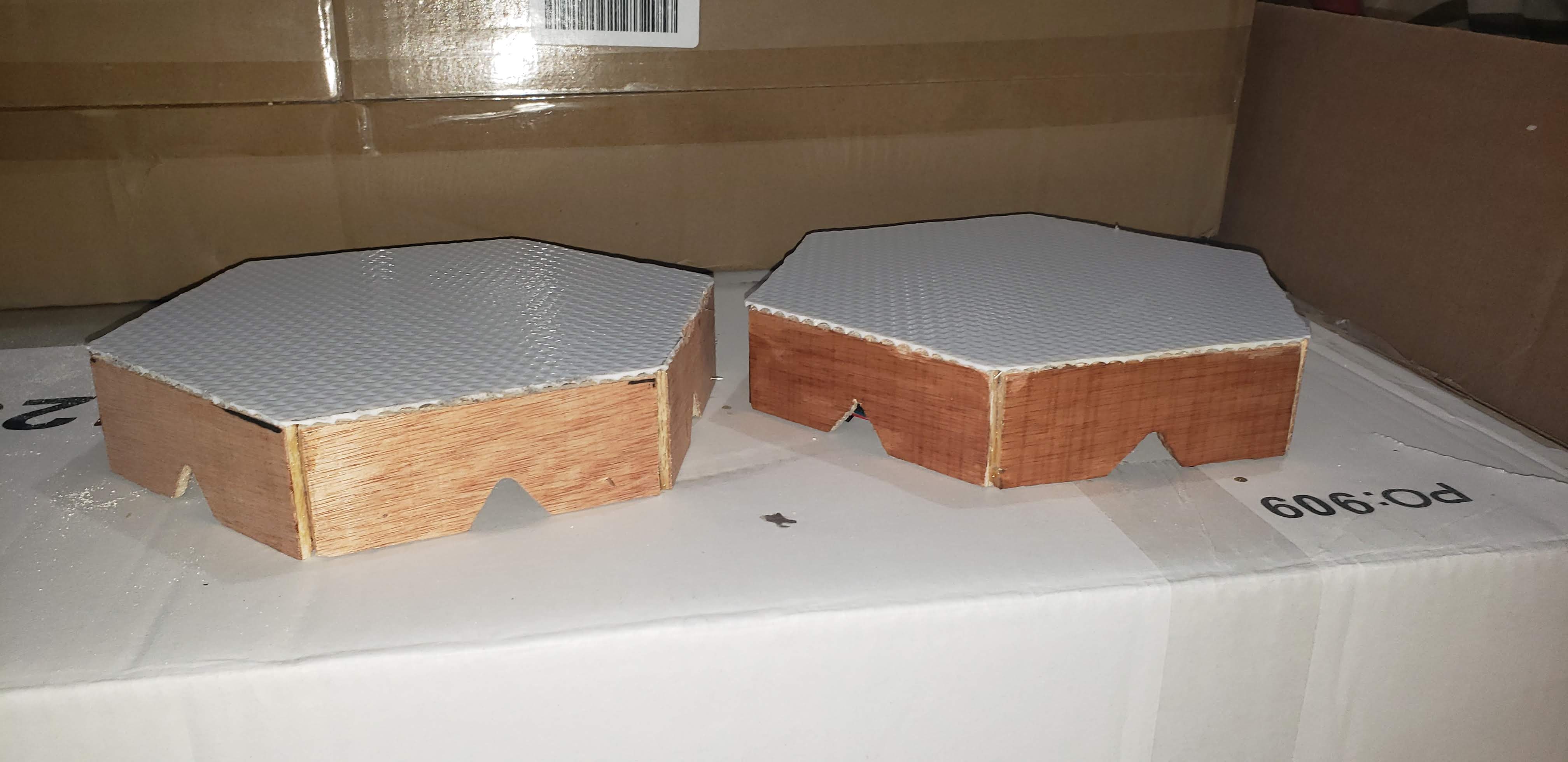 A before and after comparison of the wood without and with varnish.
After letting the varnish dry, I needed to combine the hexagons in a way such that it’d be sturdy on the wall, while satisfying my goal of it being transportable. My initial idea was to put each hexagon on push pins against the wall.
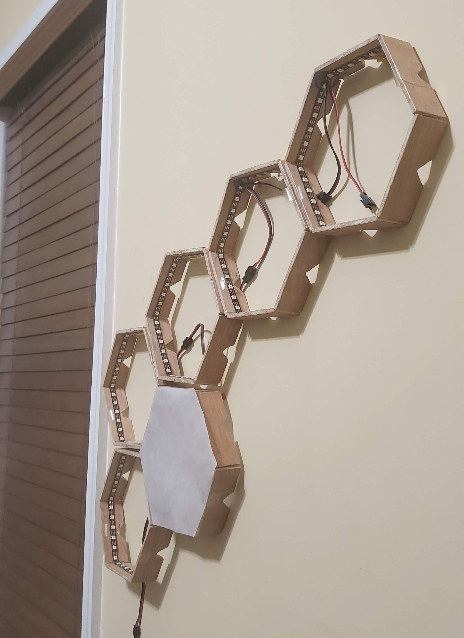 My initial setup for the display. This was done before the acrylic was put onto each unit. Each hexagon rests on two push pins, but the hexagons themselves are not connected beyond wiring.
This was a bad idea. I desperately wanted to get something to quickly work that I disregarded any real planning. It worked for the moment, but once I touched one of the hexagons, it all came crashing down. The impact put stress onto the soldering points and I had to resolder many connections.
The more thought out solution was to push pin the hexagons together so that they collectively function as one item, providing a temporary yet sturdy solution. Then I could put this display on push pins against the wall. The stability of this structure was so much better. It wasn’t perfect, but it allowed for modularity while maintaining structural integrity.
The last little touch I added was a QR code right below the display. This QR code led to the web app controller, making the display more easy to use.
Reflections
This project drained me. But it was so worth it. First of all, it looks amazing - I don’t think any image or video can act as a substitute for seeing it in-person. Second, I learned so much from this project. I used vim exclusively, which made me appreciate just how powerful it is. I implemented parallel processing everywhere - a necessity to get the display in sync. I (sorta) learned about electronics and am not as clueless anymore. And so much more. I improved my skills on technologies I was iffy about before - Flask, Heroku, git, Systemd, and so many more.
Looking back on my goals, I think I did a pretty good job. On the non-negotiables, I’m pleased with everything, though the modularity of the system is not amazing since it is not super easy to switch up the design. I also wished that anyone could control the music for the display, but for now, it only works with my account (changing it would require me to find ways to deal with Spotify’s two-factor authentication and I’ll leave that for another day). (EDIT January 21, 2021: I actually spent some time fixing this so anyone can use their Spotify account. Now nothing depends on me!)
Quick shoutout to my family and friends who helped me along the process - having others provide feedback on my progress motivated me to keep going.
There was so much I wanted to write, but I tried keeping it to major and interesting points. If you are interested or have more questions, reach out to me at contact at vinaybhaip.com.
Please consider following this blog if this post interested you. Until my next project, see ya!